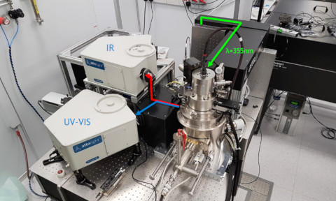
T-CEM Facility
The Time-Resolved Cathodoluminescence Electron Microscope (T-CEM) facility at the Centre for Disruptive Photonic Technologies offers time-resolved optical spectroscopy of materials beyond the diffraction limit. In T-CEM, a focused electron beam (2-10 KeV) hits the sample and generates various forms of excitations in the sample. The T-CEM then collects secondary electrons (SE), photons (i.e. cathodoluminescence, CL), and electron-beam-induced-currents for analysis. While a continuous electron-beam is typically used, a pulsed electron-beam (<10 ps) can also be harnessed to study the temporal characteristics of sample materials.

Access
The facility can be accessed by NTU users, non-NTU academic users, and commercial users, but different rates are charged. Before users are allowed to self-operate the equipment at the facility, they are required to attend a training session and pass a test. To request a measurement or training session, please contact the facility manager (Dr. Jinkyu So, [email protected]).
T-CEM Specifications
- Accelerating Voltage: 2-10 keV
- Operation Mode: CW (80 pA – 60 nA) or pulsed (< 10 ps)
- Spectroscopy: UV-VIS (180-1100nm), IR (600-1700nm)
- Time-resolved analysis: UV-VIS (Streak camera, 200-850nm), IR (TCSPC with InGaAs/InP APD, 900-1700nm)
- Quantum measurement: VIS (Si APD, 400-900 nm), IR (SSPD < 2000nm)
- EBIC: 6 contact pads
- cryo-: 10K – 350K
- Pump-probe: pump (λ=355nm, ~7mW), delay line (2ns)
Operation Modes
In continuous (CW) mode, T-CEM can generate hyperspectral maps by concurrently recording the spectra of collected photons at each pixel positions while electron-beam is moved. Figure below shows one such example where T-CEM generated a luminescence spectrum (Fig. 1b) and a spectral map (Fig. 1d) from an array of slits in a gold film. Figure 1c and 1d shows the secondary electron image and spectral map at the wavelength of 680nm of the slit array. The same can be obtained in the infrared spectral regime (down to 1.7µm).
In the time-resolved mode, a pulsed electron-beam is generated by a pulsed laser shining on the tungsten tip of the electron source and time-resolved information of the generated pulsed luminescence is acquired by either a streak camera (UV-VIS) or a TCSPC (time-correlated single photon counting) electronics with a single photon detector (VIS or IR). The system also features an electron beam induced current (EBIC) mode that is compatible with the low temperature cryostat (down to 10K).

Figure 1. (a) SE image of a slit array in a gold film. (b) CL spectra of the slit array. In CL mapping mode, a set of (c) SE image and (d) spectral map are acquired concurrently.
References
- Xin Yu Chin, Ajay Perumal, Annalisa Bruno, Natalia Yantara, Sjoerd A. Veldhuis, Laura Martínez-Sarti, Bevita Chandran, Vladimir Chirvony, Alencious Shu-Zee Lo, Jinkyu So, Cesare Soci, Michael Grätzel, Henk J. Bolink, Nripan Mathews and Subodh G. Mhaisalkar, “Self-assembled Hierarchical Nanostructured Perovskites Enable Highly Efficient LEDs via Energy Cascade”, Energy & Environmental Science 11, 1770, (2018)
- D. Cortecchia, K. C. Lew, J. K. So, A. Bruno, and C. Soci, “Cathodoluminescence of self-organized heterogeneous phases in multidimensional perovskite thin films”, Chem. Mater., 29, 10088 (2017)
- Shoujun Zheng, Jin-Kyu So, Fucai Liu, Zheng Liu, Nikolay Zheludev, and Hong Jin Fan, “Giant Enhancement of Cathodoluminescence of Monolayer Transitional Metal Dichalcogenides Semiconductors”, Nano Lett. 17, 6476 (2017)
